thargrav
Well-Known Member
I'm a EE, and probably with a lot more experience than you have, and I still do stupid stuff.

so my two drains were tied together electrically through the heatsink!
R1 = 22k resistor
R2 = 100k pot (use the middle and one of the end pins)
R3 = 4.7-10k resistor
C1 = 2.2 micro-Farads capacitor
Q1 = N-channel MOSFET
All components available at mouser.com.
The 555 can be a cmos 555 (LMC555) or a regular 555 if you like. Q1 is any standard MOSFET (or NPN transistor, like 2n2222) with a current rating of at least whatever your motor is going to suck (mine draws 100 mA). The diodes are standard silicon diodes. The two wires going the pot are connected to its middle pin, and one of the two end pins (which one determines if turning clockwise increases or decreases speed). I have drawn two options for the output stage. I prefer option 1 because MOSFETS are much more efficient, but they can be hard to find in physical stores.
Make sure your Q1 is oriented in the right way (D,G,S for MOSFET, or C,B,E for NPN) by looking at the data sheet or packaging for the component!
Rocketman768 This looks like something that I could actually pull off. Thanks for your posting. But, I'm not an EE and am a little lost on the mouser site trying to narrow down your parts list to the thousands of flavors available. Is it too much to ask for catalog descriptions/#'s of the parts list? Also on the diagram are two diodes that I don't see on the list. What flavor of these should I use?
Thanks,
Tom
Thanks rocketman. Even if the numbers have changed, at least i can figure out what the new item number will be. This will be fun!
It's an unlabeled diode:As I am putting this together from your build diagram, I noticed that there is an unlabeled diode/resister? that bridges the motor leads. Is this an R1, 1 or 3, or a diode?
Diodes: 1N4933-E3/54
I don't believe so.If I pursue the Mosfets option #1 that you recommend, do I need the R3 resister?
nmfree said:It's an unlabeled diode:
I don't believe so.
Yes. Manufacturers like to be special unique butterflies about package pin positioning sometimes.In other words does G always goes to position 3 on the 555 regardless of it's position on the mosfet?
")
That's correct.The only doubt i have is the capaciter. The capaciter has a long wire and short wire. I hooked the short wire to ground and the long wire to terminal 6. Is this correct? The data sheet said the long wire is positive.
Before you start changing anything, I'd suggest you finish mocking up the whole thing (glue your magnet to the fan, etc.) and actually try it out with your flask/jar/vessel and your stir bar. Right now with no load the fan might seem to be spinning too fast, but the added mass of the magnet, the stir bar, and the liquid in the flask will help slow the motor down.I built this on a bread board using the values on the front page. My fan goes from a medium speed to a fast speed. I need to get it to go slower. Either i have hooked something up wrong or i need some different values on some of my components.
I am guessing i need to go up on either r2 or c1. Any suggestions?

What is the purpose of sinking both the .1 and 22 mf capacitors from the source to ground?


Bumping this old thread, hopefully someone's can help me out.
The mosfet linked by op is not made anymore, so does anyone have a part # for an equivalent?
I tried making this dual stir-plate that @Magialist shows in the two attachments, and had trouble.I realize this thread is a few months old but here's to hoping someone is around to listen. First let me say thank you Rocketman for sharing such a simple to implement design!
I built upon this design to make a dual-stirplate using identical components to yours with the exception of a 556 dual timer instead of the 555. I wired up each half of the 556 just like your 555 and it's working great with one minor exception.
The only issue I'm having is that if I turn *either* potentiometer knob then *both* fans respond. I can't figure it out as the 556 halves are supposed to be completely isolated with the exception of Vcc and ground. I've triple checked the circuit and aside from the 556 itself there's nothing crossing from one half of the breadboard to the other so I can't figure out why this is happening.
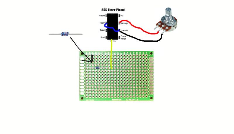
I've attached a wiring diagram for my breadboard in case anyone thinks they can help. Also the higher level circuit schematic in case you need the 556 pinout. This isn't the exact physical wiring of my board in it's final state, but it does match electrically. I made this easy to read, symmetrical version for pre-planning the circuit, but in the final layout I spread the components out and relocated some connection points for easier routing inside my box. Again though, it's electrically representative, just easier to read.
Thanks in advance to anyone that can point out what I've done wrong. If we can figure this out I'd love to post more information about my stir plate in case anyone else is interested in building a double.
Edit: So after posting this I got the idea to study the circuit diagram a bit instead of just studying my breadboard looking for mistakes, and I have a guess at the problem. For the record my capacitors are non-polar electrolytics because that's all Radioshack had. As such I'm guessing the voltage at Pin 2 is bleeding down through the "left" cap, back up through the "right" cap and affecting Pin 10 (or vice-versa). I should be able to prevent this with another pair of diodes, one between each cap and ground, to prevent any flow between those halves. Does that seem to make sense? I think I'll swing back through Radioshack tomorrow to give it a try as I can't see any other method for voltage on one half of the circuit to cross over to the other. If anyone else sees anything please let me know.
Hi !! It's an old but GREAT and very usefull thread !!!changing the way the capacitor is charged and drained is key to be able to change the pulse width from 0 to 100%. I ended up building it like this:
you need one more diode but don't need R1.
It works like a charm.
Kai
Try this: http://braukaiser.com/wiki/index.php?title=PWM_Coltrolled_Stir_Plate_DesignHi !! It's an old but GREAT and very usefull thread !!!
My diy stir plate is controled by an LM317 and it's frustrating not to be able to rotate the fan at lower speeds.... I read the entire thread and will definetlly try rocketman768's schematic.
I'd also like to make the change proposed by Kaiser (changing the way the capacitor is charged and drained) but, as an eletronic noob, I cannot do that without the schematic/picture and it's not available anymore. Any help ??
Thanks in advance
Hey, thank you !!!!
Enter your email address to join:
